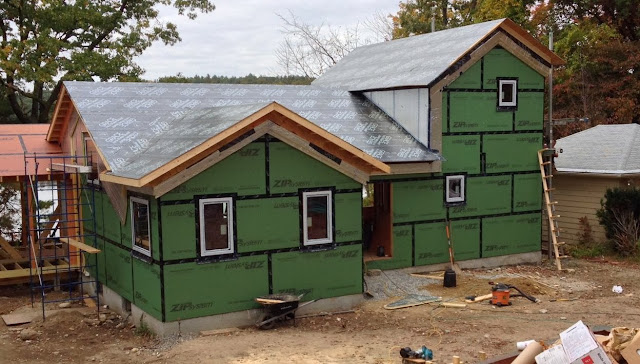
Friday, November 15, 2013

Heat loss calculation

I'll be using a ductless mini-split heat pump to heat the house.  A heat pump is a device that moves heat from a colder area to a warmer area, just the opposite of the way heat flows naturally.  An air conditioner is a heat pump as it takes heat from a cooler area (inside your house) and moves it to a warmer area (the outdoors). If you've ever stood outside next to an air conditioner, you've probably felt the hot air exhaust.  That's the heat it pulled out of the indoor space.

Now imagine you took one of those air conditioners that sits in a window and instead of taking it out in the winter and storing it in the basement, you just turn it around in the window so that the hot exhaust air blows into your house. Well, now you'd be using your air conditioner heat pump to heat your house. Please don't actually try this as window air conditioners are not designed to work in that situation but with a little tweaking manufacturers have, in fact, made heat pumps that work quite well for heating.

Modern heat pumps are more like central air conditioning systems where the compressor and the blower are split such that the compressor sits outside the house and the blower is inside, with tubing running between them. A very nice bonus is that these units are designed so that with just the flip of a switch they can run backwards and cool the house in the summer.

To decide what size heat pump I'll need, I first need to calculate the rate at which heat leaves the house. I'm not going to go into all the details of how that's done but here's a link to the spreadsheet that I built to do the calculation. It's worth a look if you're at all interested in the details.


The calculation showed that it will require about 12,000 BTUs of heat per hour to keep the house at 72°F when it's 0°F outside. To put that in perspective, that about the amount of heat that two 1500 watt space heaters generate (12,000 BTUs per hour = 3512 watts). So, in theory, a couple of portable space heaters will be able to heat the whole house on a really frigid day.


So why not just buy a couple of cheap space heaters to heat the house? Well, space heaters work by directly converting electrical energy into heat energy. So a 1500 watt space heater requires 1500 watts of electricity to generate 1500 watts of heat. A heat pump, on the other hand, uses electricity to move heat from outside to inside and it turns out that a modern heat pump only requires about 500 watts of electricity to move 1500 watts of heat into your house. So using a heat pump I'll be able to heat the house for a third of what it would cost to heat it with space heaters (aka resistance heaters).

One other thing I saw on the the spreadsheet was how much heat will be lost through each area and I was surprised at how much heat will be lost through the floor into the basement. By increasing the insulation in the floor I should be able reduce the overall heating load to below 11,000 BTUs/hr.


The upshot of all this is that I'm going to try to get by with a single small heat pump, specifically the Fujitsu High SEER 9RLS2 which is rated at 12,000 BTU/hr when heating. For those rare nights when it gets really cold I may need to augment with a space heater but hopefully those nights will be few and far between.

UPDATE 11/24/2013

I've updated the spreadsheet to reflect additional insulation in the floor which reduces the total heat loss, and to somewhat take into exfiltration, which increases the total heat loss. Exfiltration is simply interior air that leaks directly out of the house through the myriad of tiny cracks and holes that exist in any house.  Of course, any interior air that leaks out is replaced by cold exterior air that leaks into (infiltrates) the house. The problem with calculating heat loss due to exfiltration is that there's really no way to do it.  At best there are rules of thumb which were mostly developed in the days when houses were an order of magnitude leakier than this house will be.  At some point we will do a blower door test which will tell us how leaky the house is when it's depressurized by a powerful fan but there's no rigorous way to extrapolate from that number to the actual leakage the house will see.

So I made a more or less wild guess that the actual exfiltration would be about one tenth of the value we get from the blower door test, which itself is just an estimate at this point.

An empirical observation though:  I was in the house today when the wind was really howling (white caps on the lake) and the outdoor temperature was in the 20's.  Inside the house, it was at least 20 degrees warmer and there wasn't a trace of a draft.  And the house isn't even completely sealed yet.  There are still open holes where the electrical wiring goes through the walls.  And the interior insulation has yet to be installed.


Monday, October 28, 2013

Overhangs and wall insulation

In standard construction, the overhangs/eaves are created by simply building the roof planes to extend beyond the tops of the walls. This makes the carpentry simple but but makes it difficult to air seal and all but impossible to insulate outside the sheathing.  Building the shell of the house without overhangs solves both of those problems.  The corners where the roof planes meet the walls can easily be taped and the whole house can be wrapped in rigid insulation.


But the aesthetics of a traditional style house requires overhangs. As mentioned in the previous post, the top layer of plywood is installed in such a way as to extend beyond the roof plane.  The plywood then needs to be supported as shown in the picture below.  Looks simple but the carpentry has to be done carefully in order for these faux overhangs to align properly with the roof planes.


In the picture below the overhangs on the left side are complete. On the right side, you can see one of the "ladders" waiting to be installed.


As you can see in the pictures above, the windows were also being installed at the same time the overhangs were being built.  With the windows in, the crew can now complete the application of the polyiso (the rigid foam insulation) to the walls.  For the walls, I've opted to use 4" of polyiso, rather then the 6" on the roof, providing an insulation value of R-24 to the walls.  On the interior the stud cavities of the walls will be filled with dense-pack cellulose which will yield about another R-13.  With the sheathing, interior finish and the foil-facing on the insulation, the total insulation value of walls will be about R-40 when complete.


The polyiso is held tight to the house by screwing strapping through to the studs inside, similar to the way the plywood on the roof is screwed all the way through to the rafters.  The strapping also provides a base for attaching the siding.


Weather-tight!


Finally a word about how foil helps to reduce heat transfer. The three mechanisms of heat transfer are conduction, convection and thermal radiation. Insulation's primary job is to reduce heat transfer via conduction through the walls, the roof and the floor.  The air barrier that prevents the conditioned air inside a house from escaping is the primary defense against heat loss through convection.  And a shiny surface, like foil, reduces heat transfer via thermal radiation.  Thermal radiation is why you feel hot when standing near a fire, and why you can feel cold in an uninsulated house even when the heat is cranked up. In the latter case, you are radiating to the cold walls.

All surfaces radiate heat to a degree and all surfaces absorb radiant heat to a degree.  Foil surfaces radiate and absorb less than other surfaces and that's why they reduce heat transfer. A key word here is surface. If the foil is sandwiched between two other materials it can't radiate/absorb. So in the roof assembly the foil facing on the polyiso doesn't help at all.  But on the walls where the strapping will hold the siding away from the polyiso the foil facing will help a bit.  I'm counting it as about R-2 but that's really a guess.  If anyone knows better, please leave a comment and let me know!


Friday, October 25, 2013

Roof details

The roofing assembly we've chosen is somewhat complicated.  Working from the bottom up, the first layer is the sheathing - in our case the red Zip board.  Properly taped, the Zip system should provide an air barrier that is the key to minimizing air leakage into and out of the house.  In the case of the roof, air leakage tends to be out of the house as the air pressure high in a house is greater than it is lower in the house due to the stack effect.


The roof with just the sheathing

Later in the roof assembly screws will be driven through the Zip board and into the rafters below. Unfortunately this results in penetrations through the air barrier. To prevent this from compromising the air barrier we applied a layer of Ice and Water Shield - a membrane designed to seal around and nails and screws driven though it.


Polyisocyanurate rigid panel
Photo courtesy of Fine Homebuilding

Above that goes 6" of rigid polyisocyanurate (polyiso) insulation which in our case means 3 layers of 2" thick boards. The insulation value of polyiso is generally quoted as R-6 per inch, so 6 inches will contribute R-36 to the roof.  If you want a sense of how complicated building science can get check out this paper that examines how the R-value of polyiso can vary over time and temperature.

One thing I would have done differently had I thought about it ahead of time, is to have spec'ed fiberglass-faced polyiso ather than foil-faced. The foil is a vapor barrier and will keep the roof assembly from drying to the exterior. Also the foil will hinder cell phone reception inside the house.


On top of the ISO goes another layer of sheathing, in this case just regular plywood. This will be the sheathing to which the shingles will be nailed. The plywood is attached with long structural screws that go all the way through the sheathing, the insulation and the original Zip board and into the rafters. You can see the heads of the screws in the picture below.  You can also see that there are quite a lot of them.  These are, of course, the aforementioned screws that required the Ice and Water membrane on the Zip board.


Now I'm lucky if I can hit a stud in a wall behind a half inch of drywall so how, you might wonder, do the carpenters manage to hit the rafters through two layers of sheathing and 6 inches of insulation? Well, it's a bit of an art, from what I can tell, and they do sometimes miss and have to adjust.

And therein lies the story of one of those moments of panic that, I'm guessing, happens in every custom building project. The plywood went up on a Friday. The next day it was raining and when I made my daily check on the house, the roof was leaking in multiple places! It appeared the Ice and Water membrane wasn't even sealing around the screws well enough to keep the rain out, let alone provide an air seal.  David assured me this wasn't normal and guessed that when some of the "screw misses" had been backed out, some of the holes that resulted had not been properly sealed.  On Monday, the crew went over the roof, found multiple such holes and sealed them.  Luckily it rained again that night, so we were able to determine that the leaks had indeed been fixed.

Here's a detail at an inside corner where you can see the roof assembly on edge.  Just below the plywood you can see the edges of the three layers of polyiso.  Just below the polyiso you can see the black Ice and Water Shield folded down over a course of vertical polyiso installed at the top of the walls.  That blob of spray foam up in the corner is there to plug some gaps where the polyiso comes together in the valley on the roof .  The plywood extends beyond the polyiso to form the roof overhangs.


The leaks were gone but I still had a a concern about the screws that hold the plywood down.  Being situated on the east end of the lake the wind hits the house pretty hard.  During a big storm it's easy to imagine rain getting forced up underneath the shingles.  The screws are drilled tight to the plywood, but if water were to get under the shingles, I worry that water could wick down along the screws and get into the insulation. I'm probably being paranoid but I went ahead and had another layer of Ice and Water membrane applied to the plywood.


Wednesday, October 9, 2013

Windows and doors arrive!


The windows and doors arrived today.  Overall they look great.  Yaro sent two people to uncrate and help unload them, and then to install one window for instructional purposes.  Dave and crew took advantage of the extra hands to get the big window into the house and installed in the rough opening.

For the technical details refer back to the post Windows and Doors

September 10: A truck takes a container
with my windows to a port somewhere in Europe.
Photo courtesy of Yaro Window and Doors.


October 8, the container arrives in my driveway
  
The windows are screwed directly to the bracing.
It took about 30 minutes just to extricate the windows
before we could start unloading.


The big window in the house and waiting to be
installed.  Those black round things are the suction
grips that make it a lot easier to manage these
quite heavy windows.


Leveling and shimming the first window.


The trim is actually dark but is covered with a
white protective tape.


U-factor 0.13 = R-value of 7.7
COG stands for center of glass so the glass itself has
an R-value of 11.3.  The overall R-value of the window
is reduced because the R-value of the wood frame is
probably closer to 4 or 5.


The clips that hold the window to the framing.


Close-up of a clip.

Thursday, September 26, 2013

A bit of foam

Ideally this would be the order of events, now that the framing is done:
  1. Install the windows.
  2. Apply the rigid foam insulation to the walls.
  3. Apply the water shield membrane to the roof, running past the edge of the sheathing all the way to the outside of the foam on the walls.  Hopefully water will never get to that membrane, but if it does, you want the water to flow to the outside of the foam.
  4. Apply the rigid foam to the roof.
  5. Apply another layer of plywood above the roof foam for nailing the shingles.
  6. Shingle the roof
  7. Build the porches.
But the windows aren't here and aren't due to arrive until October 2nd.  So by installing a bit of foam just in the back corner, the builders were able to get started on the back porch.


It's a bit tough to see in the picture above but there are two layers of 2" foam on that corner.  The outer layer ends about 18" below in the inner panel to keep the joints staggered.


The aluminum channel the builders fabricated
to protect the bottom of the foam from insects.

In order to start applying the water shield membrane,they've applied a bit of the foam board to
the area under what will be the eaves.


The water shield membrane covering the roof and running
out over the wall foam.


Friday, September 20, 2013

Plumbing

Plumbing sure has changed in the past 20 years.   PVC drain pipe long ago replaced cast iron, but it's relatively recent that PEX supply lines have replaced copper.

The manifold is like a circuit breaker panel for plumbing.  The red
wrench stuck to the front of the manifold can be used
to turn off the various lines all from this one box.

One question I had about PEX is whether it makes sense to insulate the hot water lines. I'm assuming that hot water in PEX tubing, compared to copper, will lose far less heat as it travels to the tap but insulating still seems like a fairly simple and low cost thing to do. The plumber said no one had ever asked for it before but that he'd be willing to do it. Nevertheless something got lost in the communication with his crew and the pipes are uninsulated. But I'll take advantage of this to do an experiment. Once I'm in the house, I'll measure the temperature at the tap before and after insulating the pipes and see for myself how much of a difference it makes.

PEX and drain/vent pipes in the first floor bathroom.


I decided to replace the only section of cast iron pipe that remained: a section that went through the wall out to the new septic system where it tied back into PVC.


While we're talking plumbing, apparently toilet technology has also improved over the past couple of decades and water-saving toilets actually work. I'll be getting this dual-flush toilet from American Standard. The big flush is 1.6 gallons and the small flush is just 1.0 gallon.

Since I'll be living on a lake I'm trying to be sensitive about how much nitrogen and phosphorus I add to the lake. I plan on getting my septic tank pumped more often than strictly required for the health of the septic system. But for that to make a difference I need to minimize how much water I push through the entire system.


Tuesday, September 17, 2013

Hot water heater

Rick working on the drain/vent lines
The rough plumbing has started. After months of obsessing research, I actually have to decide now about showers, shower heads, faucets, etc.

I'll spare you.

But the hot water heater heater is more relevant. In a tight, super-insulated house, a large fraction of the total energy usage goes toward hot water, so deciding how you want to heat your water is an important consideration. The choices boil down to: electric vs. natural gas and tankless vs. tank-type.  Oh, and possibly solar hot water as well. Greenbuildingadvisor.com has a great rundown on all the options for water heating.

Tankless at first seems very appealing. They're small; they have the promise of never running out of hot water and they don't have any energy losses while not in use.  The disadvantages: they're expensive to install, they're complicated and if they break, more expensive to repair or replace, they add a bit of extra time before hot water appears at the faucet, and they have to be sized for the worst case hot water draw.

Based on all that, I've decided to go with a tank-type.

So gas or electric? Given that I have a natural gas line running to the house, there's a strong argument that I should go with gas.  From a carbon footprint point-of-view, it's better to use gas, since a gas-fired power plant will use about 3 times as much gas to generate the electricity to heat a given amount of water as a gas hot water heater would use to heat the water directly. It's actually more complicated than that since some electricity is generated by solar/wind/hydro (better) and some by coal (worse).

But there's a new generation of electric hot water heaters that doesn't heat the water directly but instead uses a heat-pump.  These electric hot water heaters are about 2.5 times more efficient than the old style.  So 3 divided by 2.5 is 1.2.  In other words, an electric heat-pump hot water heater will burn about 20% more natural gas (at the power plant) than would be needed to heat the water directly by burning gas (in a gas hot water heater).

You can probably already see where this is going - I chose an electric heat-pump hot water heater for several reasons.

  • When you have solar panels on your roof, the monthly savings are greater if you use the electricity they generate rather than pumping that electricity back into the grid.
  • The cheaper installation costs.
  • I won't need to have a vent running through the roof to vent the combustion products of a gas unit.
  • This would have been the only natural gas appliance in the house and I like the idea of one fewer bill and one fewer company to deal with.
  • Because I have a full basement and the basement is unconditioned (outside the insulated building envelope) I won't be affected by the somewhat noisy heat-pump.
  • When the heat pump is running, it removes humidity from the air.  So I'll get a slightly dryer basement.

The particular model I chose is the GE Geospring.  It's $1000 direct from GE and there's $300 federal rebate, so it'll wind up costing me about $700 plus shipping and tax and getting a 240v outlet installed for it.

So what about solar hot water?  For me, it just adds way too much complexity - a whole additional mechanical system that has to be installed, maintained and repaired.  Plus, with the increasing efficiency of photovoltaic panels, there a growing school of thought that it actually saves money to use the roof space for additional photovoltaic panels rather than solar thermal panels.


Saturday, September 14, 2013

Oddities

Sharp-eyed observers may have noticed that the roof of the second floor is asymmetric.  In the spirit of "form follows function", the south facing roof plane is larger than the north facing roof plane in order to fit more solar panels than would have been possible otherwise.  Will it look a bit odd?  Yes.  But hopefully only a bit.

Another thing that you may have noticed is that the house appears to have no eaves.  In the more traditional method of framing a house, the roof rafters would extend beyond the plane of the walls to create the eaves.  But that would create a "thermal bridge" between the interior of the house and the exterior.  A thermal bridge is a path for heat to travel without encountering any insulation.

In this house, once the windows are installed, the entire house will be wrapped in 4 inches of rigid foam insulation and the eaves will be added after the foam in order to minimize the thermal bridging.  I say minimize rather than eliminate because there are a few penetrations that seem impossible to design away (I'm looking at you, plumbing vent stacks.)

Ultimately it should all wind up looking like this:

Front elevation by Steve Baczek

Because there will be so much insulation on the outside of the walls, there's less need for insulation in the stud cavities.  I will still be getting dense-pack cellulose blown into the stud bays but having so much insulation on the outside allowed me to specify 2x4 walls rather than 2x6.  This will give me around R-22 on the outside and about R-12 on the inside, as well as about 30 additional square feet of interior space.

At some point, I'll write a more detailed post about the wall and roof assemblies.


Friday, September 13, 2013

Interior framing

Finishing up the exterior sheathing and the interior framing.


View out from the second floor bedroom


The roof on the study nears completion


The half bath and built-in aquarium wall


Sheathed but not fully taped

Thursday, September 12, 2013

Window update

Tomas from Yaro Windows called today and said that the windows should arrive on October 2.  The exterior insulation, siding and roofing can't begin until the windows are installed because the windows are going to be installed in the plane of the wall framing and have to be sealed to the exterior sheathing before the rigid foam insulation is attached.


Wall detail by Steve Baczek


When a house is wrapped in exterior insulation, windows set in the plane of the wall framing are called "innies".  You can read more about about innies versus outies at greenbuildingadvisor.com.

Hopefully, between the interior framing, the deck, and the screen porch there's enough to keep the crew busy until the windows show up.

Speaking of windows, I've decided to move the kitchen window from the spot on the south wall right behind the counter to the upper part of that wall.   I gain a nice, high, almost skylight-like window, additional wall space behind the counter and a lot of privacy from the street.